draw polyline over point cloud civil 3d
March 12, 2018
The 2022 versions of the Autodesk programs have been out for a while at present. You have a point cloud and you need to create a surface from information technology. Well, if you accept the AEC drove, you take two options, 1) Create the surface in Civil 3D or 2) Create the surface in InfraWorks. Which one should you use?
I was working with a client recently that had this very same dilemma so I decided to exercise a fiddling testing to see how well each option does creating the surfaces. To give a little chip of background on the information set, the point cloud contains around 90 1000000 points and is an agricultural field with a stream running through the eye of it.

Overall Point Deject in Epitomize
This dataset is kind of unique as it has areas that are very flat and fairly consequent as well equally areas that vary quite a flake. Creating a single surface in Civil 3D from 90 million points would accept a massive amount of time (if information technology was even possible) and so I decided to examination this on a smaller scale. I cut out a couple portions of the point cloud, one in the expanse of the field and ane in the surface area of the stream.
Let's get to creating the surfaces. I created the surfaces for both areas using both Civil 3D and InfraWorks. In both programs, I maxed out the settings to go the all-time possible surfaces.
Creating The Surface in InfraWorks
How is this washed in InfraWorks? First, I created a new model and imported the ReCap file. Once the bespeak cloud is in the model, I used the command, "Point Cloud Terrain". This can be found on the "Build, manage, and analyze your infrastructure model" section (Big Orangish "I"), and then the "Create and manage your model" (Q-bert looking button).

Indicate Cloud Terrain Command
The settings I used for generating the terrain tin be seen in the following image. I basically gear up them to give me the all-time possible terrain I could get from the data. One time I created the surface, I then imported the surface into Civil 3D.

InfraWorks Point Cloud Terrain Settings
Creating the Surface in Civil 3D
To create a surface in Ceremonious 3D 2018, just like with InfraWorks, you must showtime import the indicate cloud. On the Insert tab of the ribbon, yous can merely adhere the Epitomize file. Once the indicate cloud is in the drawing, select it and, on the contextual ribbon tab, cull the control, "Create Surface from Signal Cloud".

Control to Create Surface from Indicate Cloud in Civil 3D
Just like with InfraWorks, I created these surfaces so they would max out the data that was available. In the command, I did not change the settings for the number of points existence used or the area to utilize (I had already cropped out smaller areas from the overall betoken cloud in Recap). The only settings I changed that would affect the data was on the Non-Basis Point Filtering section, where I inverse information technology to utilise the Kriging interpolation filter method.

Filter Method set to Kriging Interpolation
How do they compare?
To compare them, I brought the ii surfaces for each surface area into a cartoon and then created a volume surface between them. This allowed me to come across what the elevation differences were between the ii surfaces. I and so did an elevation analysis on the book surface so I can see where these differences are.
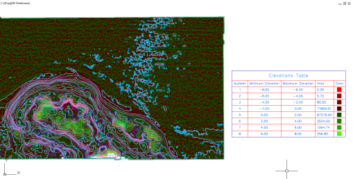
The Field
The first i I did was for the area of the field.

Comparison of Surfaces in the Field
If you wait at the numbers, you can come across that over 96% of the surfaces are within 0.i′ of each other and over 99.8% are within 0.2′. This is actually good! If I zoom in on the area of the contours (they are i′ contours by the manner, y'all can run into a piffling flake more particular.
Field Contours
The blueish contours are from the surface created in Civil 3D whereas the red contours are from the surface created in InfraWorks. One terminal comparison, lets look at the information density of the two surfaces. How many points are in each of these surfaces?
- Ceremonious 3D Surface – 356,420 points
- InfraWorks Surface – 9,993 points
To be fair, I could have decreased the number of points as I was creating the Ceremonious 3D surface just, I maxed out the settings in InfraWorks.
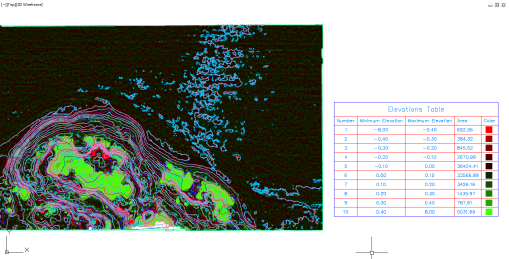
The Stream
I repeated the process for the area around the stream.
Comparison of Surfaces at the Stream
As you can run across, the numbers aren't quite equally good hither. In fact, there are areas that are off past upwardly to eight′. I did a like comparison based on these numbers and found that almost 97% of the surface was within 2′ and nigh 99% was within 4′. This isn't a fair comparison so I reran the analysis using basically the same numbers as for the field (0.1′ increments) only I lumped everything beyond 0.4′ into the same category. This is what I found:
Surface Comparison with 0.ane′ Increments
Once more, I ran the numbers and constitute that 83% was within 0.one′ and 89% was inside 0.ii′. A little concerning was the fact that over vi.7% was more than 0.4′ off.
Let'due south go alee and zoom in on the contours (again, the blue contours are the Civil 3D surface and the red contours are the InfraWorks surface). I displayed it with and without the book surface because information technology was difficult to run into all the contours at times.
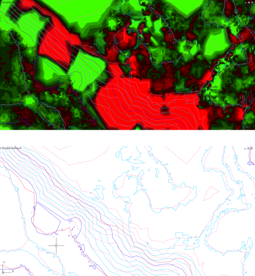
Stream Contours
The comparison in size between the two surfaces are:
- Ceremonious 3D Surface: 773,732 points
- InfraWorks Surface: 24,474 points
I don't know how to increase the accuracy of the surface created from InfraWorks any more than information technology is.
Final Thoughts
Based on the results I've received hither, which method would I utilize? Well, if the area is adequately flat and consequent (the field in this example), I would probably go with the InfraWorks surface. If there is a lot of inconsistencies in the data (the stream in this example), I would probably go with the Ceremonious 3D surface.
Remember, you tin can create an overall surface in InfraWorks, create surfaces in Civil 3D for those areas that it's needed, and so paste them all together at the end.
What are your thoughts? Have you had much experience with surfaces from point clouds in InfraWorks, Ceremonious 3D, something else all together? Did I get something wrong? Let me know what you think in the comments!
September viii, 2017
The Autodesk River and Flood Analysis Module 2022 (aka River Assay) has merely recently been released and has some major fixes that volition exist very welcomed by anyone who uses this programme. In the by there were a few bugs that were extremely abrasive that no longer exist. Keep reading to learn what they were. If you aren't moving to 2018, but you're nonetheless using the River Analysis tools, make certain to read this and so you know what to be enlightened of!
Deleted Terminal Entity Created
When the River Analysis tools are initialized in a drawing, the terminal object in the drawing that was created was deleted. That's correct, whatever that last object was – a line, a circle, a surface, an alignment – whatever it was, it was deleted. This is no longer an upshot in 2018!
If you're using 2022 or earlier, my recommendation is to depict a line in your file immediately prior to issuing any River Analysis tool so y'all know which object will be deleted.
New Reaches Automatically Created
In one case the River Analysis tools were initialized whatever drawing used in Civil 3D after that moment would have a new achieve created in it. The symbol for the reach would be placed about 0,0 then it destroys the ability to zoom extents. Not merely that, since River Analysis is now initialized in this drawing, information technology deletes the last entity created. 2022 has stock-still this problem!
If y'all are using 2022 or earlier, my recommendation is to run Civil 3D only for the River Analysis job you accept. Don't open up whatever other drawings. Once you are washed with the River Analysis task, close Civil 3D and reopen information technology and you lot should be good to go. If you initialize River Assay again, you'll need to close and reopen Ceremonious 3D again to prevent information technology from creating reaches and deleting objects.
Accomplish Drib-down Inconsistent
The drop-down to select the reach y'all desire to work on has been inconsistent at all-time. Sometimes information technology works, and sometimes it doesn't bear witness up at all. I was never able to figure out a decent piece of work around for that one. In 2018, I haven't seen any bug with the drop-down not behaving the way it should.
Where to go it?
If yous haven't been using River Assay just want to, you tin can install it from the Autodesk Desktop Application. If yous don't have access to this, y'all can too go to manage.autodesk.com, log into your account, and download it (provided you have the permissions to download and install). Otherwise, ask your software managing director or IT section for it.
Wrap Upward
If you lot are using the River Analysis tools, you would exist doing yourself a favor and doing the piece of work in Civil 3D 2018. Even if the rest of the project is on a prior version, still practice your River Assay work in 2018, consign out the HEC-RAS file, and so import it into a prior version if needed.
July 14, 2017
Creating custom parts for your storm sewer or sanitary sewer networks in Ceremonious 3D is non fun. If you've ever had to go into Part Builder, you know what I'one thousand talking about; secret variables, odd objects (what's a COL object anyways?), and sometimes things merely don't work (haven't been able to create a cut plane in Role Builder in nigh a decade). Most of the fourth dimension when people demand to create a new part for a network in Civil 3D, they end up proverb, "Whatever is already there, is probably close enough and I'll but employ that instead of doing it correct."
I have adept news for you. In the latest version of InfraWorks (InfraWorks 2018.ane) there is a new tool called the Project Infrastructure Parts Editor.
The Infrastructure Parts Editor has been around for quite a while in the Autodesk Labs (information technology was known as Project Kameleon, yes, with a Grand) but has recently graduated from labs and is now a full blown program. This tool volition allow you to create new parts for apply with InfraWorks every bit well as Civil 3D.
To admission the new tool, within InfraWorks click on the drainage tools, and then click the pencil drawing a line, and then click on the button for the "Parts Editor".
This will so open upwardly an external application called, you guessed it, the Infrastructure Parts Editor.
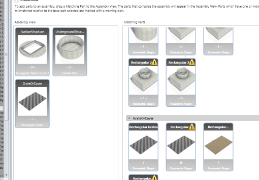
How easy is this? Basically, it's just pick and choose the parts yous want to use. When you create a new itemize (or edit an existing one), you'll see three options, Assembly, Structure, and Culvert. The parts that will exist used in Civil 3D or InfraWorks are the Assemblies. Each assembly is fabricated up of the structures or the culverts.

When y'all click on Structure, you'll see the iii different components that make up the structures: Surface Structure, Surreptitious Structure, and Grates or Covers. The Infrastructure Parts Editor has some parts already created that you can kickoff with or you lot can create your own using Inventor or Inventor LT.
Every bit you lot tin encounter in the previous image, if none of the predefined shapes work for you, yous can create a new shape template and import a .ipt or a .iam file from Inventor.
Additionally, when adding sizes to the unlike structures, in that location is an option to export to and import from Microsoft Excel. This should make editing the sizes much easier!

Export to Excel
Once all the structures have been created, they will then exist combined to make the unlike assemblies. When creating an assembly (depending on the type of assembly existence made), y'all'll only select the 3 different structure components that you want to combine together. At that place's also a section to validate the sizes (don't want to put a 5′ long grate on a 3′ long inlet).
Associates Creation – Elevate and Drop
One time all your assemblies are made, you can then publish the catalog out to either InfraWorks or Civil 3D or both at the same time.
So, what do you recollect? Are you going to give this a try? Personally, I'thou really excited near this tool and it capabilities for creating custom parts in Civil 3D.
p.southward. It also does pressure level network parts:

December 2, 2016
AU2016 has come up and gone and I'thousand really excited about indicate clouds right now. I sabbatum in a lab with Ramesh from Autodesk (using point clouds in InfraWorks) and he gave me the data set he was using as a sample. In the course, he imported the data set into ReCap, trimmed out the unneeded bits, and then brought that into InfraWorks which worked just fine.

Same Clipped Indicate Cloud in InfraWorks and Ceremonious 3D
The trouble is, if you lot bring that aforementioned clipped point deject into AutoCAD Civil 3D (or any other AutoCAD based program), the point deject is not clipped. According to the Autodesk Cognition Network, this is a known problem and they are working on fixing it however, the only solution currently listed in that location is, "For InfraWorks the betoken cloud functionality has been corrected with release 2016". That'southward not much of a solution if you enquire me but, I did happen to observe ane.
after clipping the point cloud in ReCap, export the project out. This will create a new point cloud that tin can and so be inserted just fine. To export the point deject, mouse over the House icon, the Down Pointer icon, and then click the Up Arrow icon.

Export the Clipped Project
ReCap will then ask y'all if you desire to unify the scans. I'chiliad not exactly certain what this does just I call up it combines all the browse files into one file. When I did this, I just used the default settings and clicked the "infinite ship" icon.

Huh? A space send? Really?
In one case the project has been exported, simply import that into Ceremonious 3D (or any other AutoCAD based program) and the point cloud volition exist clipped.

Comparison between original file and exported file in Civil 3D
Hopefully this volition assist someone out that's struggling with point clouds in AutoCAD. If you have fourth dimension, I would dearest to hear how you lot are using indicate clouds in either InfraWorks or Civil 3D. Leave a comment and allow usa all know!
October 31, 2016
Have you ever had two surfaces that you needed to combine together but the trouble is, at the boundary of the inner surface, its elevations don't match the elevations of the outer surface. In cases like this, if you paste them together yous can go some actually odd things going on where they are supposed to meet.
An example of this might be that you have one surface that was created from USGS data and some other surface that was surveyed. They should be close to the same elevations only they won't be exact. I oftentimes have people ask me if at that place's a way to combine them but use a buffer between. Using a buffer you won't get those most vertical triangles or triangles that become out for quite a while until they connect into the other surface.

Pasting Surfaces Issue
In the above paradigm, I have 2 surfaces, one with greenish triangles and a yellow border and one with grey contours. I need to paste them together to create a combined surface. Any surface points that are under the border of the inner surface when it's pasted in will be removed and that white, thick line represents the triangles from the outer surface that are unchanged. As you tin see, there are some odd things going on.
Since there's no way to add a buffer when pasting surfaces, what practice yous practice? Well, hither's how you do it in 5 unproblematic steps:
- Extract the border of the inner surface.
- Offset this extracted edge the buffer distance.
- Assign the elevations from the outer surface to this new object.
- Create a surface from this starting time.
- Paste all three surfaces together.
i. Extract the border of the inner surface.
You probably already know how to do this but, in case you don't, it's pretty simple. Just follow these steps:
- Brand sure the surface you want to extract the border from is using a style that actually displays the edge (you can't extract something if the surface isn't dislaying it).
- Select the surface and on the ribbon aggrandize out "Extract from Surface" and choose "Extract Objects".

Extract Objects
- Select "Border" from the options in the next dialog box (deselect anything else y'all don't desire to extract from your surface) and click OK.

Select the Border to Extract
You now have a 3D polyline in your drawing where the edge of the surface is.
ii. Kickoff this extracted border the buffer distance
Again, pretty elementary but I'll explain the steps here. On the Modify tab of the ribbon, on Edit Geometry panel, there's a control called, "Stepped Offset".

Stepped Offset
Follow the command line prompts and start it the distance yous need. When it comes to setting the elevation, it really doesn't matter what you choose as we'll set the elevation of this new polyline in the next pace. The AutoCAD Start command most likely will not work as this is probable to be a 3D Polyline and the Offset command only works on 2D objects.
three. Assign the elevations from the outer surface to this new object
This new polyline needs the elevations of the outer surface. Yet on the Change tab of the Ribbon, on the Edit Elevations console, there is a command called, "Elevations from Surface".
Run this command and select the polyline. Next you lot'll see a new dialog box asking you which surface to utilize. Select the outer surface (in this instance it's chosen "Pre-EG") and make certain you toggle ON the option for, "Insert intermediate grade break points".

Elevations from Surface Options
Your new 3D polyline now follows the outer surface exactly and we're ready for the next step.
4. Create a surface from this object.
Over again, pretty simple simply here are the steps.
- On the Dwelling tab of the ribbon, on the Create Ground Information panel, expand out Surfaces, and select the beginning option, "Create Surface".
- Name it accordingly (I would phone call information technology something similar "<inner surface proper noun> Pasting Buffer". Set any other settings yous desire (the style really doesn't thing – I would probably choose something like, "No Display" if it's an choice).
- On the prospector, expand out the new surface, expand out the definition, right click on Breaklines and chose, "Add". Select the offset 3d polyline and apply the breakline settings as desired.
And that's it. You're washed.
5. Paste all three surfaces together.
Now, that you have done all that, we are prepare to paste them all together. Y'all can past them into the original outside surface but I'm not a fan of that. I would much rather have the outside surface remain intact in case I demand to employ it for something else. I typically volition create a new surface (see step four for the steps to create a new surface).
On the Prospector tab, aggrandize out the new surface, expand out definitions, and choose "Paste". Select the surfaces you want to paste in. The order yous paste them in is very important every bit whatever is within the edge of the incoming surface will completely overwrite everything within it. The lodge we will apply hither is 1) Outside surface ii) Buffer surface 3) Inner surface.

Paste Order
The following sequence of images show the progression of the new surface equally the other three surfaces are pasted in. I left in the thick white line from earlier as a reference.
As you can see, that buffer works very nicely. You can compare this to a surface that only has the outer and inner surfaces pasted in.

Same surface without the buffer surface
What exercise y'all recall? Is this something yous might use? Leave a comment if you practise this a different way. I ever beloved to hear about dissimilar ways of accomplishing things!
The data set I used is from the training transmission "A Applied Guide to Civil 3D 2017" by Rick Elis. You lot can social club a copy from his company CADapult if you would like one. This is the volume I employ in my classes.
October 24, 2016
If you've downloaded the Civil 3D 2022 v1 Enhancements and tried using the Swap Pressure Network Parts control, you might have seen some odd things happening…

Shifting Parts When Swapping Parts (picture from Autodesk)
Autodesk has released a hotfix for this. It's a simple fix, just download a file and swap out the one on your system with the new file. The hotfix can exist plant Hither.
September 8, 2016
One of the things I've struggled with in the by is some of the reports don't work well with Internet Explorer 10. I wrote up a blog mail on how to adjust the settings within Internet Explorer to emulate IE9 but information technology'southward non fun to do. A reader of my blog mentioned an addition for Google Chrome that allows it to emulate Net Explorer, it's called IE Tab.

This is really simple, set Chrome equally your default browser, run the report, click on the button on the toolbar, let the content, and you're golden!

September iv, 2016
Using Pressure level Networks? Install Your Service Packs!
Posted by Brian Hailey under Civil3D | Tags: C3D2016, C3D2017, Ceremonious 3D, Civil 3D 2016, Civil 3D 2017, Curve Piping, Data Reference, Follow Surface, Pressure, Pressure Network, Pressure level Pipe, Service Pack |
[5] Comments
If you are using Pressure Networks within Civil 3D, do yourself a favor and install the new service pack for Ceremonious 3D 2022 (SP3) and Civil 3D 2022 (SP1.1). These fix several pressure level networks issues which I'll talk about here.
A petty bit of background, a few weeks ago (not sure of the verbal date) the Civil 3D production team released service pack 1 (SP1) for Ceremonious 3D 2017. In that location were some bug with it so they pulled information technology downwardly and so but last week they re-released it as service pack i.1 (SP1.1). Equally of this writing, it'due south non available on the Ceremonious 3D back up website HERE but I was able to download it via the Autodesk Desktop App. It should show up eventually. The Civil 3D 2022 SP3 is available at that link.

Service Pack in the Autodesk Desktop App
Then what are the issues that are stock-still and why are they important? Yous can read upwardly on the changes included in the service packs here: 2022 SP3 and 2022 SP1.one. The 2 issues I'll exist referring to in this post are:
- An issue that acquired unexpected behavior when using grips to edit pressure level network pipes in profile view has been resolved.
- An outcome has been resolved where edits to the level of a pressure network were not retained when the pressure network was data-referenced
Reference Issue
Let's talk nearly number 2 beginning as, in my stance, that's the large one. When you create a pressure level network and edit the elevations of the piping by either putting in a vertical bend or have it follow the surface, when you data reference that pipe into another drawing, the piping comes in straight.

Reference Issue
As you lot can see in the previous image, on the left is the source drawing containing two pressure pipes. One of the pipes has been vertically curved and the other has been set to follow the surface. When referenced into another drawing, they come up in straight as can be seen on the right.
After installing the service pack, simply open up the same drawings and synchronize the references. You'll see that the referenced pipes are the same as the source pipes.

Reference Issue Resolved
Grip Issue
The second item I will be discussing here is the issue with grip editing. This isn't always an issue but can exist in sure cases. Showtime off, what is the outcome? Well, if you ready a pressure pipe to follow a surface and and then use grips to edit the elevations of the unlike parts, sometimes the grip will be applied to the side by side grip instead of the selected grip.

Grip Edit Result
Later installing the service packs, this is no longer an issue.

Grips Working Correctly
So, what causes this issue in the first identify? This only seems to exist an issue if the alignment and the pressure pipe are going in opposite directions. When y'all create the alignment from force per unit area network, make sure the pipes and the alignments are going the aforementioned way. Fifty-fifty with the latest service packs, if they are going opposite directions, you lot'll still see a small-scale effect, the last grip on the pressure level pipage won't display.

Missing Grip
Every bit far as I know, there's no way to edit that grip in this view, you'll need to create a different alignment going the contrary direction to be able to edit it. In other words, information technology'southward still a good idea to have your pressure pipes still go the same direction as the alignment but information technology'south not quite as important.
August eighteen, 2016
Geometric Center and Civil 3D
Posted by Brian Hailey nether Civil 3D | Tags: Civil 3D, Ceremonious 3D 2016, Civil 3D 2017, CUI, Drafting, Geometric Center, Object Snap Menu, Object Snaps, ObjectSnap, Snap, Snap Menu, Snap Override, Snap Overrides, Snaps |
[iii] Comments
AutoCAD 2022 saw the introduction of the Geometric Center object snap. If you aren't familiar with this snap, information technology basically will snap to the "geometric eye" of an object, such equally a polyline. What's the geometric middle? Well, it'south the centroid or center of mass. The problem is, this snap is non available in the Snap Override menu within Civil 3D 2022 or 2017.
<annotation>It was pointed out to me that this doesn't work in 2016. The shortcut carte in the ACAD.CUI that is installed with Civil 3D 2022 is incomplete likewise. If y'all are using 2016, you'll demand to re-create the menu from the ACAD.CUI that gets installed with AutoCAD, non the i installed with Civil 3D. Open up the ACAD.CUI in the transfers tab and re-create information technology over that mode. </annotation>

AutoCAD vs. Civil 3D
Yous'll too notice that in AutoCAD, you get the icons showing what the different snaps exercise whereas in Civil 3D, you don't. If yous want to enable this, you'll need to replace the Civil 3D Snap Override menu with the AutoCAD version. To practice this, get into your CUI editor (type CUI at the command line if you haven't been at that place before).
In the CUI, scroll towards the bottom (I hid the Control List to go far easier to see), expand out Fractional Customization Files, ACAD, and Shortcut Menus. Under the Shortcut Menus, right click on "Object Snap Cursor Bill of fare" and choose "Copy". At present that the AutoCAD version is copied, we'll go replace the Ceremonious 3D version with the AutoCAD version. Collapse upwardly the Partial Customization Files and expand out Shortcut Menus (directly under CIVIL), right click on Object Snap Cursor Menu and choose Delete.

Replace the Civil 3D menu with the AutoCAD menu
Once the old carte du jour has been deleted, right click on the Shortcut Menus and cull Paste. This will paste the AutoCAD version of the menu that nosotros copied into the Civil CUI file. Now, simply close the CUI editor and return to Civil 3D and be happy with your new snap overrides menu.

Civil 3D with the new snap card
August 14, 2016
Civil 3D 2022 SP 1 – And the Glyphs it Brings
Posted by Brian Hailey under Civil3D | Tags: Civil 3D, Civil 3D 2022 Service Pack 1, Glyph, labels, Obnoxious, Override, Service Pack, Service Pack 1, SP1, Style, Alarm, What'southward New |
[9] Comments
<note: In Civil 3D 2018.one, there are some new system variables that deal with these glyphs so go install it now! Just kickoff typing "labelover…" and the autocomplete will finish it off for you>
So, you lot've downloaded Civil 3D 2022 Service Pack one to set those pesky issues. Which problems? These issues. Nifty, so you close out of Ceremonious 3D, install the service pack, and the side by side time you're in your drawing, you observe a whole bunch of warning symbols!

Glyphs Glyphs Everywhere!
What are these things? Well, they are a new feature that was added to Civil 3D 2022 in Service Pack i. They let you know when a label has a text override. If you lot agree your mouse over the glyph, it volition tell you what information technology's there for.

Tooltip when hovering over glyph
Merely similar the other alarm symbols in Civil 3D, when the drawing is regened (run the REGEN control), the glyphs will always go back to a certain percentage of the screen size (I'm not exactly sure what that is and I don't have a ruler handy to exercise the calculations).
I can meet these symbols pretty much taking over a cartoon so, how do y'all turn them off? Well, at that place are two means:
ane) Don't override the text in your labels. I didn't say they were both GOOD ways.
ii) Plough off all the symbols like this in your drawing. I didn't say either way were GOOD ways!
Yup, if yous want them turned off, yous have to disable the display of ALL of these alert symbols (Pressure Network Design Checks, Alignment Tangency Checks, Alignment Design Criteria Violations, Contour Horizontal Changes, etc.). To do this go into your AutoCAD OPTIONS and on the AEC Editor tab yous'll meet a department called "Solution Tips" (these symbols are called "Solutions Tips" apparently). The two radio buttons permit yous to control if you see the tips when drafting (i.due east. in your drawing) and when your plot.

Solutions Tips
I suppose the other option is to simply not install Service Pack 1. If you aren't having any of the issues it says it fixes, and you don't want these obnoxious symbols all over your drawing, I don't meet whatever super compelling reason to install it.
What do you call back? Do you lot like the symbols? Do you hate them? Personally, I'll give them a try. I e'er recommend to people that when Autodesk does something new to the software, give it a calendar month. If afterward a month y'all don't like it, then get back to the fashion it was. Now, if I could only figure out how to go back without uninstalling the service pack…
Source: https://civil3dplus.wordpress.com/tag/civil-3d/
0 Response to "draw polyline over point cloud civil 3d"
Post a Comment